Valve
Introduction
In steady state the valve is only occasionally used, typically with a specified pressure drop. But in dynamics mode the valve is a key unit operation. As in real life, it is used to regulate flow or pressure. It is a fundamental building block in that it establishes a relationship between flow rate and pressure gradient, which results in a realistic model. In dynamics mode the valve is nearly always set to use a flow equation rather than a fixed pressure drop.
Sizing
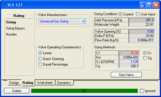
For valve manufacturer the choices are:
- Universal Gas Sizing - The flow rate is linked to the frictional pressure gradient according to the Fisher Controls Universal Gas Sizing Equation. This includes vapour choking, where the flow rate may at some point stop increasing if the pressure gradient continues to increase. Liquid choking is not currently modeled.
- Simple Resistance Equation - The flow rate is proportional to the square root of the frictional pressure gradient. There is no choking.
The valve operating characteristics allows the valve control type to be selected:
- Linear: Valve travel is directly proportional to the valve stoke.
- Quick opening: Large increase in flow with a small change in valve stroke.
- Equal Percentage: Equal increments of valve travel produce an equal percentage in flow change.
The default is linear, though equal percentage is perhaps the most commonly used valve control.
The valve opening can be changed on this page so that it can be used to size the valve. In general, do not try to directly control or manipulate the valve opening with a spreadsheet or controller, but rather manipulate the valve actuator desired position (which will drive the valve towards to desired position, factoring various other considerations as well).
The valve can be sized from the current conditions (e.g. if it was just added and the outlet pressure was updated), or from a set of user conditions.
You can also choose what combination of Cv (valve liquid size coefficient), Cg (valve gas size coefficient), Km (pressure recovery coefficient) and C1 (C1 = Cg/Cv) to specify but all four values must be determined. By default C1 has a value of 25 (ranges from 16 to 37 generally) and Km = 0.001434 * C1.
The valves comes with sufficient default options and values, and at minimum a new valve just needs the Cv to be specified.
Sizing Bypass

If Model Valve Station is checked, then a bypass valve and block actuators are also modeled. The bypass valve acts exactly like another valve in parallel with the main one. It is common enough that it is directly supported by the valve without to actually use another valve instance.
Nozzles

The nozzles page allows the valve elevation and inlet and outlet nozzle elevations to be set. These are used in static head calculations. The diameters are used if the valve is also modeling a section of pipe.
For operations like valves, the feed and product nozzle elevations are generally left to default to the same elevation as the valve. However, they may be changed to introduce artificial elevation differences in the absence of detailed additional equipment.
Specifications

The valve contributes equation to the simultaneous pressure flow network. It can add an equation which fixes the pressure drop across the valve, as well as a flow equation which links flow to frictional pressure drop. In most situation, (only) the flow equation option will be used, since it is most realistic.
This view also shows the valve size and relevant values and can be used to size the valve based on current values.
Checking Check Valve will prevent reverse flow through the valve.
Pipe

The valve can also be used to model as section of pipe. This pipe model performs a relatively simple and fast calculation, but is sufficient in most cases to model the pressure loss associated with a section of pipe.
It calculates a friction factor using the information provided and uses that to add a contribution to the valve flow equation (which must be used to be able to model a section of pipe). Assuming turbulence results in slightly faster calculations because the friction factor is fixed. Turbulent pipe flow is common.
Note that this pipe model may not provide accurate results for multiple phase situations and does not model choking or any complex transient phenomena such as shockwaves.
The Disable Valve can be used to model a section of pipe only, with no valve. This is handy for solving pipe network systems or studying a vessel drain through a pipe under gravity for example.
The pipe option is generally used where the pipe can have a significant impact on flow or pressure. While it can be configured in every valve, there is typically minimal benefit in doing so.
Holdup

This view is common to dynamics unit operations and shows the contents of the volume inside the unit operation as well as other generic relevant information such as nozzles.
It is recommended that the valve volume be left at zero. Adding in a small valve volume results in more complex equations which is rarely worthwhile. It is often simpler to just increase the volume of a nearby vessel slightly if need be.
Actuator

A valve is made up of several components. Usually there is a control signal which is then used by an actuator to change the valve accordingly. This is important because actuators have a dynamic response, and also the actuator may stick or fail, and thus prevent the valve from reaching the desired position.
The actuator can be made to fail, and whether this results in the valve remaining open, shut, or staying at its last position, can be set on this page.
If the valve has worn trim, the it will not fully close.
Valves should be controlled by setting the actuator desired position, rather than the valve opening directly.
Actuator Station

If a valve station is modeled, then actuator settings for the bypass and main valves, as well as the block valves can be set here. The valve station can also model the action of two block valves in series with the main valve.
Stripchart

This view can be used to quickly create a stripchart. Select a group of variables from the drop down and then remove unwanted variables from the matrix before pressure the button to create the stripchart.
< Process Stream | Index | Pipe >