Logical Operations

Introduction
In additional to the spreadsheet, cause and effect matrix and event scheduler, Petro-SIM also provides an additional range of operations for implemented process logic.
Set

The set operation maintains a relationship between two variables. For example, one stream pressure can be set to be always 10 kPa higher than another. In steady state it calculates either the source target or offset, depending on what is known. In dynamics mode, since all variables are always known, the multiplier and offset are always specified, and the target value is always updated from the source, if need be. Generally the target is a specified variable, whose value is then updated.
Selector

The selector accept a number of input variable sources and based on its settings, determines one output value.


It can calculate the minimum, maximum, median, average, sum, product or quotient (first value divided by all the others). A hand selection (Hand Sel) option is available for selecting a specific input. For each input value as well as the output value, a gain and bias can be applied (PV used = Gain * PV + Bias).
Transfer Function
The transfer function operation (signal block) can be used to implement or effect control transfer functions, and allows a combination of integrator, lead, lag and second order functions to be combined. The integrator option sums up: InputSignal * StepSize / Integrator Period.
Digital Point

The digital point takes an optional variable source and an optional output target. It can be Off, in Manual mode, or in Automatic mode.
Manual mode: If the operation is latched, the output will be On or Off as set and remain so. If the operation is set to pulsed mode, it can temporarily pulse on or off. For example, if the Output is set to On, and the operation is set to Pulse Off with a pulse duration of 2 seconds, then clicking on Off will send an Off (zero) output signal for two seconds before the digital point will revert back to being On.
Automatic mode: The PV value is compared with a threshold and the digital point is either on or off or pulsed for the duration depending on the result of the comparison.
The digital point can also show alarms based on the PV value. The deadband is used to ensure that an alarm does not rapidly cycle between on and off if the PV value is closed to the alarm value.
The digital point is also an easy way to for example turn pumps in the flowsheet on or off.
Boolean Not Gate

The Not gate takes a single input, reverses its value, and sends it to one or more outputs.
Boolean And Gate

The And gate send a true output only if all inputs are true. If any one is false, its output is false as well.
Boolean Or Gate
The Or gate send a true output if one or more of the inputs are true. If they are all false, its output is false as well.
Boolean XOr gate
The XOr gate send a false output if all inputs are either false, or all inputs are true. If some but not all inputs are true, ts output is true as well.
Boolean OffDly Gate

This unit operatoin waits the designated amount of time before passing an on value through.
Boolean OnDly Gate
This unit operatoin waits the designated amount of time before passing an off value through.
Boolean Latch Gate

If there is only one process variable source, then it determines the latch value.
If there are two process variable sources, then the first one sets the latch (makes its output go to true and stay there) and the second one resets it (makes the output go back to false again) it. Assume both inputs are false, and the latch is zero (output is zero). If the first input goes to true, the latch output will go to true and remain there even if the first input goes to false again. It will reset (go to false) only if the second input goes to true (provided the first input is not true anymore either).
Boolean CountUp Gate
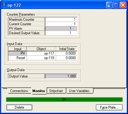
Two inputs are required. The second input acts as a reset flag, and if true, it reverses the output value. If it is false, the first input value is compared with the output alarm. If it is equal then the current counter is incremented. If the Current Counter reaches the Maximum Counter, then the Output value gets pushed out.
Boolean CountDown Gate
This works similar to the count up gate, except that when the fitst input is compared with the output alarm and is equal, then the current counter gets decremented instead of incremented.
Adjust
The adjust unit operation adjusts one variable to drive another towards a specific target. In dynamics mode, doing this is far more complicated because timing and transient phenomena play a role as well. Hence adjust unit operations are ineffective in dynamics mode. Use a controller instead.
< Controllers | Index | Other Topics >