Vessel
Introduction
This section covers the vessel unit operation, which refers to the separator, three phase separator, tank, condensers and reboilers.
Differences from Steady State
Vessels in dynamic mode behave differently than in steady state mode. Some of the differences include:
- Phases are not necessarily at the boiling or dew point in dynamics mode.
- Vessels can overflow and drain and all vessels can have up to three phases.
- Outlet phases are determined by flow direction, and nozzle elevation and diameter, as explained in the basics. So the vapour outlet can contain liquid if the vessel overflows.
- The phases are not necessarily at equilibrium. Dynamics mode supports efficiencies.
- The vessel size and geometry are very important in dynamics.
The vessels all behave basically the same way.
Parameters

For best realism, the vessel Delta P should be specified to be zero. Frictional or static head contributions for feed attachments should be properly modeled using elevations or valves or such. The feed pressure drop specification is always applied in dynamics mode.
The duty should preferably be controlled to maintain a desired temperature or composition somewhere, along with level control where applicable. Subcooling specifications are ignored in dynamics mode.
Sizing

In steady state the vessel size or geometry is often of little importance. But in dynamics mode this can impact the levels and how they and the pressure in the vessel changes.
Certain geometries support a boot. This is a smaller section at the bottom of the vessel, usually with a much smaller diameter and height than the rest of the vessel. It is generally used in three phase elevation so that a small amount of a second liquid phase such as water will have sufficient level so that it can be readily removed, rather than forming a think spread out layer at the bottom of the vessel.
The weir option may also be available for certain geometries. The weir inside the vessel divides it into two chambers. Chamber two is generally smaller and allows the lighter liquid phase to overflow so that it can be easily drained away instead of possibly forming a too think layer at the top of the vessel liquid.
Nozzles

Note that the contents of the vessel products are as determined by the levels inside the vessel and stream nozzle elevations and diameters, as explained in the basics. The elevations also impact static head contributions, when active.
Heat Loss

Depending on the type of vessel, the heat loss may be set to None, Direct Q, Simple or Detailed. Direct Q means that a fixed heat flow is specified. If the simple model is chose, the heat loss is typically calculated from
If the ambient temperature is not specified, the default ambient temperature value from the Integrator view Heat loss page is used (and also updated as it changes).
If the detailed option is chosen, then the equations are far more involved. This option allows Metal and Lagging properties (thickness, heat capacity and conductivity) to be specified. The thickness for either or both of these can also be set to zero if they are not present. The inside and outside convective heat transfer coefficients also need to be specified, with defaults provided.
In both cases the area is calculated from the vessel geometry.
The heat loss calculation and values are a separate issue from the vessel duty stream. The heat loss is applied to the entire vessel contents by default. If the vessel phases are not in equilibrium because of efficiencies then the duty effectively applies to the portion of the material that is flashed in equilibrium before being mixed back with the remainder of the material.
Level Taps

Multiple level taps can be added to the vessel. Each level tap can sense the elevation of one or two liquid phases inside the vessel, but it can only sense the elevation in a certain range (the PV High and PV Low). The tap may not be installed to extend the full height of the vessel, or may deliberately be set to only measure low levels at the bottom of the vessel. If the vessel is using a weir, then the level tap can also be installed in chamber 1 (before the weir) or in chamber 2 (after the weir).
The level tap input signal (coming from the level and PV high and PV low), gets converted to an output signal in the range of OP Low to OP Low. So the final value that is available to a controller say could be manipulated to be a percentage (in the range of say 0 to 100%) or to act like an actual level or elevation (in which the type can be set the Length for example).
Specs

When a vessel is newly created or has never been run yet, it will initialize its contents when the integrator is started. This can be done by combining the product streams and flashing. A dry startup can also be done. In this case the vapour inside the vessel is determined from the attached streams and is not set to be at its dewpoint as steady state would do. User specific initial values (a composition, temperature and pressure) can also be provided. Unless dry startup is selected, the initial amount of liquid is determined by the liquid volume percent. If two liquid phases are present, they are ratioed according to the relative amounts of the two phases.
Note that at any time, specifically while the integrator is not running, a value can be entered for Liq Volume Percent This will adjust the amounts of liquid and vapour in the vessel as desired. This is a quick convenient way to quickly change or reset the level in a vessel without having to wait for it to naturally change.
The fraction calculator (so called because it calculates the outlet phase fractions) can be changed from its default value of Use levels and nozzles to Emulsion Liquids. The emulsion calculator assumes that for two liquids, while still being immiscible, the phases are not separated. Both phases will exit the vessel for any nozzle that is underneath the top liquid levels.
Condensers also allow for a Reflux Flow / Total Liq Flow specification. This is only to be used in simple column models. Otherwise condenser sections should be modeled more rigorously as demonstrated in some of the Samples.
The Vessel Pressure can be made a specification in the network of equations that are solved simultaneously. This is determined by the state of the checkbox. The vessel pressure always appears blue, allowing the user to possibly change it or set it to an initial value before starting the integrator for example.
The Add/Configure Level Controller will install a level controller if one is not installed already. It will be connected to a valve in the main liquid outlet line if one is present, or to the stream itself. Rough initial tuning values will also be provided.
Holdup
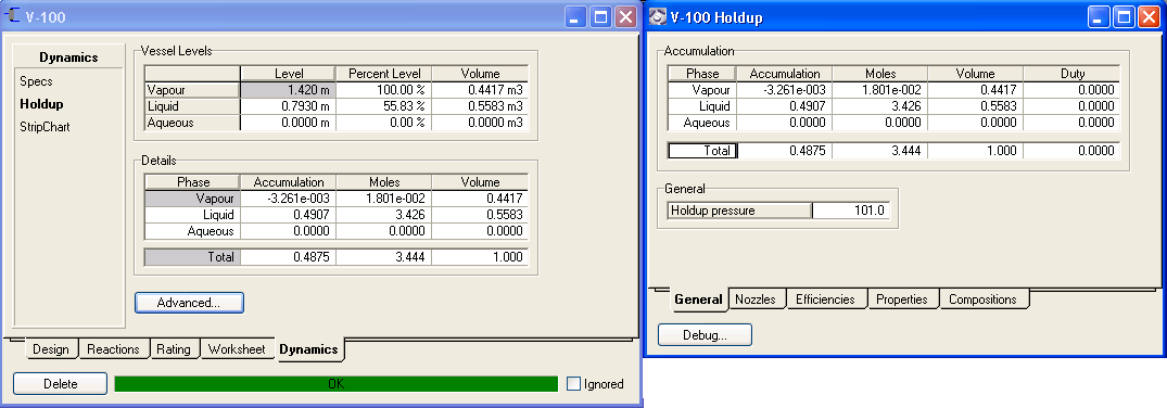
This view is more for information purposes. It allows the details of exactly what is inside the vessel to be examined.
It also provides a way common to many unit operations of accessing elevation and various nozzle settings.
Nozzles and efficiencies are discussed in the basics.
StripChart

To easily add a strip chart, select a group of variables from the drop down, then edit the list of variables by deleting undesirable ones and click the button to create a strip chart.
Duty
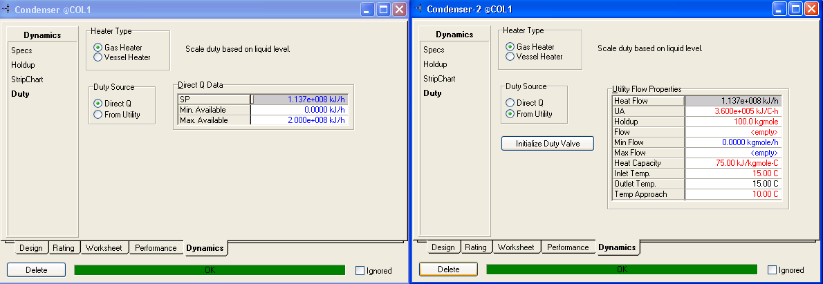
The presence of the duty page depends on the presence of a duty stream.
If a gas heater is used, then the duty is scaled down as the level decreases and less heat is transferred to the vessel contents. If a vessel heater is used then the full duty is applied.
For a Direct Q duty source (i.e. use the energy stream value directly) the value may be provided, as well as a range for possibly scaling the duty based on level. This mode is commonly used in vessel to control the duty.
If the source is a utility, the duty is calculated and updated in the duty stream. The calculation is done using the flow and properties provided for the utility fluid. Pressing Initialize Duty Valve results in the duty valve using the current vessel temperature and energy stream duty to calculate temperature and UA values for the duty fluid so as to result in similar duties being calculated as when only the energy stream was used directly. This makes it easy to switch to using a duty fluid, whose effect can be controlled by manipulating its flow rate.
Condenser specifications such as degrees of subcooling are not supported in dynamics mode because they are pure design specifications. Instead the temperature inside the vessel needs to be controlled.